The CSA Propylaea Project
Harrison Eiteljorg, II, 2013. https://doi.org/10.5284/1022574. How to cite using this DOI
Data copyright © Harrison Eiteljorg, II unless otherwise stated
This work is licensed under the ADS Terms of Use and Access.

Primary contact
Harrison
Eiteljorg, II
Center for the Study of Architecture
Box 60
Bryn Mawr
PA 19010
USA
Resource identifiers
- ADS Collection: 1591
- DOI:https://doi.org/10.5284/1022574
- How to cite using this DOI
Final Report, CSA Propylaea Project: Mechanical Drafting Explanation
Making views of the sides of a block may seem simple, and it generally is, but there are some conventions that may not be obvious. Since it is important for a clear understanding of the object that the positions of a protrusion or depression or any other feature on one view should align with the adjacent views, the views are related to one another so as to make that alignment possible. Thus, each view is made as if the block or other item could be rolled to bring each surface, in succession, to the top for a simple plan view. This yields views related to one another with the common edges adjacent. However, the resulting views are quite different from what one might expect if operating on the assumption that the block or item remains stationary while the draftsman works on one side and then another, moving around the block and always simply drafting as if looking at that side alone.
The following drawings should help to explain. First just look at the first five simple 3D views to make sure you understand the nature of the block in question. The top and bottom are labeled, to help you understand the block. Make sure you do understand the geometry of the block before looking at the next series of images; they may be a bit confusing.
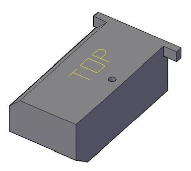
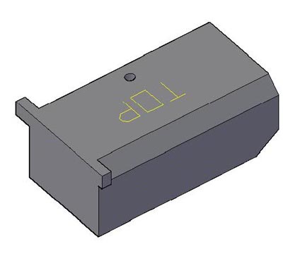
Fig. 1 - Top Views
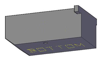
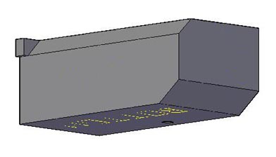
Fig. 2 - Front Views
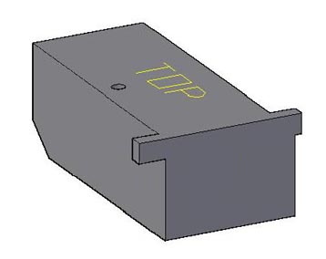
Fig. 3 - Top/Front View
The next series of views of the block - the same views as above - shows a label on each surface to identify it. The labels, though, are oriented as in the simple plan views that would be made in the process of drawing each side as part of a comprehensive set of mechanical drawings of the block. It may be mystifying at first, but you need simply to think of each view as created by rolling the block as required to put the surface in question on top. That is the orientation for the mechanical drawing, and it results in the text being seen properly right-side up and right-on-right.
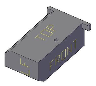
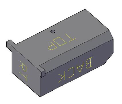
Fig. 4 - Top Views
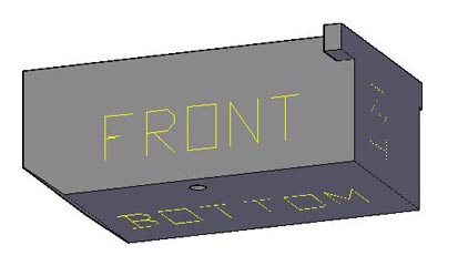
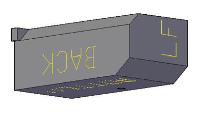
Fig. 5 - Front Views
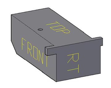
Fig. 6 - Top/Front View
The last drawing here is similar to the kind of mechanical drawing that might have been made of the block shown in the illustrations above. Each side has a plan view, but in each case the orientation is carefully done as if the block were being rolled side-to-side or front-to-back so that the nearest edges (e.g., the top edge of one view and the bottom edge on the view above) are the same edge of the block. As a result, anything on the edge should align in the two adjacent views. This is not the most intuitive way to draw the surfaces, but it helps to prevent errors, and it is clear and direct (though confusing if one compares the view of the back of the block to the view one might obtain by walking around the block and making a series of head-on plans). Note that the label for each face is properly right-to-left and right-side-up here. (Note also that there are broken lines to indicate the position of the hole passing through the block, where appropriate, but other broken lines that might show hidden edges have not been included.)
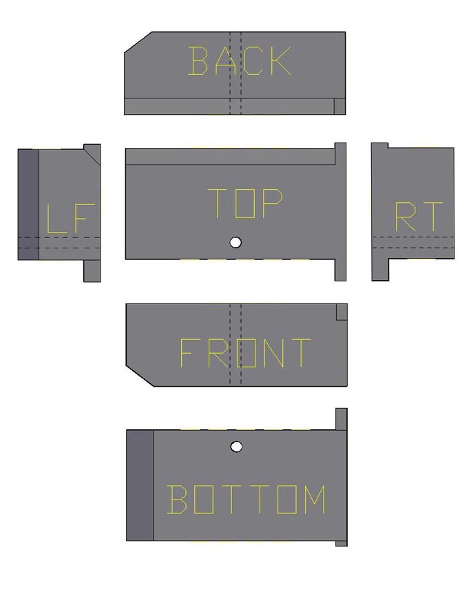
Fig. 7 - Mechanical Drawing View
As a series of views in a mechanical drawing, of course, the drawing here fails. There should not be the gray shading, and there would normally be a host of dimensions. (Of course, dimensions placed between views would apply to both adjacent views!) Nevertheless, anyone attempting to make sense of the AutoCAD drawings of blocks of the north wall of the Propylaea must understand these mechanical-drafting conventions.
- Title: "Final Report, CSA Propylaea Project: Mechanical Drafting Explanation
- Author: Harrison Eiteljorg, II and the staff of CSA, Box 60, Bryn Mawr, PA 19010, (e-mail: user nicke at (@) the domain csanet.org; tel.: 484-612-5862)
- Original file name: mechdraw.html
- Revision history: Since this document is part of the CSA Propylaea Project Final Report and has been archived with the Archaeology Data Service, changes should not occur. Serious mistakes may be corrected; if so, clear indications of corrections will be included. First posted: 3 August, 2000. Last updated (formatting only): July, 2012. Prepared for ADS archival storage June, 2013.
- Internet access: This document was first prepared for propylaea.csanet.org, operated by the Center for the Study of Architecture and Harrison Eiteljorg, II. It has been turned over to the Archaeology Data Service for archival preservation.
- Long-term availability: This document or its successors will be maintained for electronic access indefinitely.