Older Propylon
Harrison Eiteljorg, II, 2016. https://doi.org/10.5284/1039967. How to cite using this DOI
Data copyright © Harrison Eiteljorg, II unless otherwise stated
This work is licensed under the ADS Terms of Use and Access.
Primary contact
Harrison
Eiteljorg, II
Center for the Study of Architecture
Box 60
Bryn Mawr
PA 19010
USA
Resource identifiers
- ADS Collection: 2111
- DOI:https://doi.org/10.5284/1039967
- How to cite using this DOI
Overview
All the documentary evidence from Eiteljorg's work was assembled by him for archiving by the Archaeological Research Institute (ARI) at Arizona State University. That evidence was entirely in computer form, and it has been moved to its present location at the Archaeology Data Service as a consequence of some difficulties with the prior archival repository. Although the original work was done without anticipation of the use of computers, all the data were put into computer form and archived for future access. The computer files generated in the course of the work and others generated for archival storage are defined and described in this document. All were made by Eiteljorg or under his direction. They include scans of drawings and notes made on site, scans of slides taken on site at various times, a CAD model which was constructed over time, beginning in 1985 and only concluded in 2003 (with the addition of links to external data that are no longer supported by the software), and data tables constructed to augment the CAD file. There are also some black-and-white negatives that have been scanned; they were used for photogrammetry work on the Mycenaean wall in 1989. Finally, there is a data table to identify the scanned photographs.
The files referenced above are the following:
- CAD model: oproprxiv.dwg
- Data tables to augment the cad file: OPattDATA.csv (attributes of individual blocks) and OPcomments.csv (information related to notes in the CAD drawing that relate to parts of the model, not individual blocks)
- Scanned photos and the csv file about them: NewOPphotos.csv
- Image files for the:
- correspondence (letters between Eiteljorg and officials in Athens)
- field drawings (drawings actually made in the field)
- field notes (notes made mostly, but not exclusively, while working in Athens)
- redrawings (drawings made in an office or work room, based on the original field drawings, but utilizing some drafting tools)
It should be noted that all scanned materials other than photographs were scanned in the offices of CSA, using a HP OfficeJet R80 and PhotoShop 5.0; settings were for gray-scale at 300 d.p.i., unless noted otherwise. The resulting files were stored as uncompressed TIFF files in PC order. File names are in the format op##xx.tif, where ## is a rough chronological sequence and xx indicates the type of document (co=correspondence; fn=field notes; fd=field drawings; and rd=re-drawings). Some scans have an added "a" to the name; they are scans of photocopies of the original images with added notations or measurements. Files made from documents made later than 1975 have a two-digit addition to the name to indicate the year of the original document ("87" for 1987 and "90" for 1990).
An explicit statement of copyright has been placed in the CAD model by CSA and should show upon opening the model. It reads, "Copyright, Center for the Study of Architecture, 2004. CSA holds the copyright to this document/model. The right of any scholar to access and use the model for true scholarly purposes is expressly granted. In addition, CSA expressly grants to the Archaeological Research Institute (ARI) at Arizona State University the unlimited right to use the model for true scholarly purposes and to permit other scholars to access the model for scholarly use. Commercial use of any kind is only permitted with the written permission of CSA; commercial use includes any use for publication or public lectures that are not free to all."
The first use of computers for the work was the creation of a CAD model. The survey work on the older propylon had been accomplished in 1975 with tape measures, line levels, carpenter's squares, and plumb bobs. A transit was used to take levels. No more sophisticated survey instruments were used. (The material south of the SW wing of the Propylaea was not independently surveyed by Eiteljorg; material there was included in the CAD model via Dinsmoor's published drawings.) As a result, data entry into the CAD model was carried out primarily by using simple geometric shapes and altering them as required by the measurements.
In 1989 photogrammetry was used to survey some of the stones of the Mycenaean fortification wall. The data from that survey work was put into the model with explicit coordinates obtained via photogrammetry. (The Photogrammetry work was carried out with the Rollei program called MR2, and the discussion of that work may be found in a CSA Newsletter article from August of 1990 (V. III, No. 2) by Harrison Eiteljorg, II, entitled "Using the MR2 Program and Tolerating Frustration." Holes and cracks in southern wall blocks of the upper courtyard of the older propylon were entered into the model with the use of AutoCAD's plane transformation process.
All measurements are in meters. All the blocks of the primary study area — the area lying within the external corner of the Propylaea formed by the southern wall of the central building and the eastern wall of the SW wing — were measured to the nearest mm., and dimensions obtained from the model should be taken to be precise to the mm., although some may consider that to be more precise than warranted by the methods used.
Dimensions of the blocks of the Mycenaean wall, obtained via photogrammetry, should be taken to be precise to the nearest cm., as should dimensions and positions of cracks and holes in the southern wall blocks of the upper courtyard, which were placed with the aid of AutoCAD's plane-transformation process. The material in the secondary study area — south of the SW wing of the Propylaea — was not fully measured by Eiteljorg. Dinsmoor's published drawings and notes were used to create the portions of the model pertaining to that area. Precision should not be assumed to be tighter than the nearest 3 cm. because of the dependence upon scaled drawings for data transfer.
There is at least a theoretical possibility that Eiteljorg will further modify some of the files remaining in his possession. If he does so, the archive will be provided with updated information, and such modifications will be noted. Interested scholars, however, may wish to contact Eiteljorg directly (see http://csanet.org to find his address or write to him c/o CSA, P.O. Box 60, Bryn Mawr, PA 19010, USA) to learn if there have been updates not yet communicated to the archive. Other scholars who use and augment any of the materials should also provide the new or changed data to the archive.
Other software used for archived materials includes but it not limited to MS Word (Word 97, Windows version), OpenOffice Writer (version 1.0), FileMaker (versions 4.0, 5.0, and 6.0 for data tables), MS Access (Access 95 and 97 - for earlier versions of some data tables), and PhotoShop (release 5.0, Windows version - for scanning paper records). Other, unspecified software was used for the scanning of photographs (by an outside contractor, Luna Imaging of Culver City, CA). The standard ASCII character set (ISO 8859-1, Latin 1) and English have been used throughout.
AutoCAD Model
The AutoCAD model, oproprxiv.dwg (file format for Release called AutoCAD 2000) began in a very early form of AutoCAD, probably version 2.5 or 2.6, but Eiteljorg no longer remembers the version number. Much of the model had been created previously in another CAD program (ARRIS) and portions in still other early CAD programs on Macintosh and PC machines, but the AutoCAD model was constructed entirely from the data; no transfer of information from the prior program was accepted.
The file has been migrated automatically from version to version of Autodesk's DWG file format via built-in AutoCAD processes. AutoCAD 2000 is not the most current version of the program, but it is the most current version in use at CSA at the time the material was first deposited. (CSA, the Center for the Study of Architecture, has been the organization directed by Eiteljorg since its founding in 1985; see http://csanet.org.)
Database linkage has been tried, and various rendering possibilities have been tried. There may be artifacts of those two processes in the CAD file, but there are no database links currently maintained in the AutoCAD file except as noted below (no implicit links at all), and there are no intentional data items for rendering.
Line colors and line types in the CAD model have no meaning by intent. Only layer names have been used to convey information about the blocks that have been put into the CAD model. As a result, colors or line types can be changed for any given drawing, on screen or paper, without compromising the data content.
The 0,0,0 location is at the juncture between the south wall of the upper courtyard of the older propylon and the parastas wall that rests on the steps leading from lower to upper courtyard. "Drawing north" is aligned to the parastas wall. There is a second coordinate system (in AutoCAD parlance, a user coordinate system) called north that aligns the y-axis of the model with the north arrow (with the same 0,0,0 point as the base coordinate system), making the model align itself properly with the compass points. (It should be noted, however, that the north arrow has not been carefully aligned via computations and may be off by a few degrees.) There are no other user coordinate systems saved with the model.
AutoCAD model scripts
There were scripts that had been compiled for use with the AutoCAD model; they had been created by Eiteljorg to make it easier to call up those portions of the model that were related by date, material, and/or model style. Those scripts are not supplied here since they are not required. However, in order to create similar systems to call up limited portions of the model as required for specific purposes, users should make an effort to understand the use of layer names recommended by CSA and discussed in the document available here, "The CSA Layer Naming Convention." Any serious user of the model should consult the CSA Layer Naming Convention to understand how best to manipulate the model for maximum utility.
There were also prepared views, as made possible by AutoCAD. They are not archived here since their use has been limited by Autodesk.
Data tables linked to CAD model
There are two external data tables (archived here as .csv files), one with data items that apply to individual blocks in the model and one with comments about the model more generally. The data items about blocks are in a data table called OPattDATA.csv. Model layers named with a D in the first position contain icons that indicate the blocks for which data items have been supplied and the number of the individual data item explicitly linking the model item to the data.
Notes of a more general nature are contained in another table OPcomments.csv. Layers named N plus a numeral (e.g., N1, N2, etc.) have icons and numbers to indicate the portion(s) of the model discussed and the comment number of the table entry.
CAD Layer Information
A user may refer to the appropriate CAD layer(s) to find the references to external data table entries. Similarly, a user of the data tables will find there the names of the layers needed to see which items are referenced. This system — icons in the CAD file with explicit links to data tables — is intended to make it possible for the files to be migrated in the future to new formats without fear of losing information.
Crucial to the use of the CAD model is an understanding of the layer-naming system used. Each layer is named with a string of characters — 18 in all — and each character or group of characters indicates an attribute of the material on the layer. (This system is governed by the CSA Layer Naming Convention" which may be found here: http://csanet.org/inftech/csalnc.html)
The names may be parsed with this list of characters and attribute meanings.
Character One: type of layer
- C - Cracks or other damage to a 3D block or surface (may be used with plan layers if the surfaces in question are horizontal)
- D - Data links
- E - Contour lines only (no other characters in the name); EC has contour lines with text labels for the elevations (no other characters in the name). Neither of these layers follows the rules for longer layer names.
- H - Holes or sockets in a 3D surface (may be used with plan layers if the surfaces in question are horizontal)
- L - Labels (text) for individual views or paper drawings. LVIEWS may be unclear. That layer contains a circle showing the locations of vantage points for prepared views (with the 0,0,0 point always being the aim point). Thus, invoking the AutoCAD VIEW command to call up stored views requires consulting this layer (and at least a few plan layers) to understand the orientation of the stored views. (C or CL will be appended to view names to indicate close-up views.) Note that the layers beginning with L do not follow the rules for layer names explained here.
- M - Modeled (3D) surfaces
- N - Annotation links; N plus one digit. There is no meaning to the digit; there are too many notes to place on a single layer; so there are multiple annotation layers. (The layer NARROW, with no other characters, contains a north arrow and the letter N only)
- P - Plan, 2D-only drawing (lines, not surfaces)
The distinction between model layers and plan layers is critical. Model layers contain 3D elements --surfaces, whether vertical or horizontal. Plan layers contain only lines at an arbitrary elevation.
Data links and annotation links are icons with numbers and lines to indicate the point or area of interest.
Cracks and holes may apply to plan and/or model layers depending on the surfaces affected.
Labels are for printing out plans.
Character Two: "in-situness"
- H - Hypothetical material, the nature and position of which are uncontested
- I - In situ, undisturbed at point of original use
- J - In situ, undisturbed at point of last but not original use
- K - In situ, disturbed at point of original use by natural disaster
- L - In situ, disturbed at point of original use by man-made action
- M - In situ, disturbed at point of original use by natural events subsequent to abandonment
- N - In situ, disturbed at point of last but not original use by natural disaster
- O - In situ, disturbed at point of last but not original use by man-made action
- P - In situ, disturbed at point of last but not original use by natural events subsequent to abandonment
- S - Natural bedrock
- T - Trimmed bedrock
- Z - Not relevant
Character Three: the general type of the finding area, such as a public area, a domestic area, a military area, and so on
- M - Military
- P - Public (intended to be a very general category)
- R - Religious (sanctuary, shrine, etc.)
Character Four: the specific part of the area
- A - Area, a general designation
- C - Courtyard
- E - Entrance
- F - Fortification
- R - Road or street
- S - Sanctuary
- X - General, unstated
- Z - Not applicable
Examples: Using MF as the third and fourth characters of a layer name indicates a military fortification; PR a road in a public area.
Characters Five and Six: usage (general and specific respectively).
The first of the two letters signifies a broad category - e.g., wall, stair, or pavement for a structure; the following character narrows the range of the first - e.g., retaining, foundation, or surrounding for wall.
Character five, general use:
- P - Pavement/floor
- S - Stair
- W - Wall
- X - General
- Z - Not applicable
Character Six, specific use, may take on different meanings according to character five:
- B - Base
- F - Foundation
- J - Joint
- P - Paving block
- R - Retaining
- S - Step (including riser and tread) for stair, surrounding for a wall
- U - Uncertain, indication that the specific usage is uncertain
- V - Veneer
- X - General
- Z - Not applicable
Examples: Using MFWS as the third through sixth characters of a layer name indicates a surrounding wall of a military fortification; RESS a step of a stair in a religious entry.
Characters Seven and Eight: material.
Once again, a general category is given by the first of the two characters and a more specific one by the second.
Character seven, general material:
- B - Building stone (cut or carefully shaped)
- M - Metal
- R - Rough stone (used without careful shaping)
- X - Bedrock
- Z - Not applicable
Character eight, specific material:
- I - Iron
- L - Limestone
- O - Poros
- P - Pentelic marble
- X - General
- Z - Not applicable
The following 5 characters (nine through thirteen) indicate a starting date for the material in question, with a beginning negative (in place of a leading zero) to indicate a date B.C.E. Dates are often conventional, not intended to be taken as literal accurate-to-the-year indicators. Consulting the Eiteljorg volume (1994) is recommended for full discussions of the dates of construction and destruction in this area.
The following 5 characters (fourteen through eighteen) indicate an ending date for the material in question, with a beginning negative (in place of a leading zero) to indicate a date B.C.E. A date of 09000 here indicates something still in place and now taken to be part of the modern environment. Dates are often conventional, not intended to be taken as literal accurate-to-the-year indicators. Consulting the Eiteljorg volume (1994) is recommended for full discussions of the dates of construction and destruction in this area.
Examples:
PIREWVBO-0489-0478 = Plan version, in situ material in a religious entrance, wall veneer of cut-stone poros masonry, built in 489 B.C.E. and replaced in 478 B.C.E.
MMMFWSRL-120009000 = Modeled version, in situ but disturbed by natural events subsequent to abandonment, military fortification surrounding wall, made of roughly-shaped limestone, erected in 1200 B.C.E. and still standing.
Documentation of the layer names
A data table called OPlayers.csv contains information about actual layers in the model. It was constructed by Eiteljorg in the mid-1990s (in MS Access 95 and Access 97 and then in FileMaker 5.0 and 6.0 with tab-delimited ASCII files used as export/import format for moving data from Access to FileMaker) and finished in December of 2003; transfer to the .csv format was done in 2015. Work on this was done entirely by Eiteljorg. The table presents all layer names beginning with M, C, H, D, L, E, or N so that a user of the model may determine the nature of the material shown on the layer in question. Layer names beginning with P (plan-only layers showing the material modeled on layers beginning with M) are not included in the data table. The names may be parsed by comparing them to names beginning with M or by using the description of the layer-naming system provided above.
The system for naming layers is very rigorous and is explained above, but this table shows the actual layers made and used.
As implied above, some names have been created to by-pass the longer naming system. Layer E holds only elevation contour lines. Layer EC contains only the labels for those contour lines. (No other layers begin with E.) Layers beginning with L are labels and are named in self-explanatory ways, though LVIEWS may be unclear. That layer contains a circle showing the locations of vantage points for prepared views (with the 0,0,0 point always being the aim point). Thus, invoking the AutoCAD VIEW command to call up stored views requires consulting this layer (and at least a few plan layers for orientation) to understand the orientation of the stored views. (C or CL will be appended to view names to indicate close-up views.)
Layers beginning with N (plus a digit) contain annotation icons (see below). There are several such layers, but the names are not meaningful; the digit has no importance. There are simply annotation layers to prevent overlap of icons onto model elements.
The layer Z is an empty layer that can confidently be used as the current layer in a program like AutoCAD. It will always be empty and therefore has no affect on any view when it is made the current layer. (Those who understand the way AutoCAD treats layers will understand the importance/value of such a layer.)
Layer 0 is AutoCAD's default layer and cannot be removed. The copyright statement is on that layer and should show on opening the model. Nothing else is on layer 0.
Some other layers have been created by AutoCAD and cannot be removed. They are ACADASE, AME_FRZ, and ASHADE. Those layers contain no model entities.
Documentation of OPlayers Table:
This table was created by Eiteljorg in Access 95, migrated to Access 97 format and then transferred to Filemaker (4.0) via tab-delimited export files. It was then migrated to the 5.0 format (which is used by version 6.0 as well). It was first created in the mid-1990s and completed in December, 2003. It was ultimately transferred into the .csv format in 2015.
The table uses the standard ASCII character set.
Data field, type, and content:
- LAYER: text - layer name, unique (a layer name used in the CAD model)
- PLAN_MODEL: text - MODEL, PLAN, DATA LINKS, CRACKS, HOLES, LABELS — These are the meanings conveyed by the first character of the layer name.
- In_situ or . . . : text - In situ; General, agreed hypothetical; Eiteljorg hypothetical; Dinsmoor hypothetical; Prim(ary) use, moved, natural cause; 2nd use, moved, natural cause; Trimmed bedrock (These are the meanings conveyed by the second letter in the layer name)
- LOCATION: text - Public courtyard, Religious area; Religious entry, Military fortification; Public road (meaning conveyed by the third and fourth letters in the layer name)
- USE: text - Cistern; Gate, foundation; Monument, base; Pavement, paver; Stair, step; Stair, bench; Stair, foundation; Stair, clamp; Wall, general; Wall, surrounding; Wall, veneer; Wall, core; Wall, parastas; Wall anta (So-called); Wall, uncertain; Wall, foundation; Wall; retaining; Wall, general; Wall, terrace; Wall, joint between parastas and Mycenaean fortification wall; Wall, joint filler (These are the meanings conveyed by the fifth and sixth letters in the layer name.)
- Material: text - Cut stone, General; Cut stone, Pentelic marble; Cut stone, Poros; Cut stone, Limestone; Rough stone, General; Rough stone, Limestone; Trimmed Acropolis limestone; General, unspecified; Rough Acropolis (?) Limestone; Metal, Iron (These are the meanings conveyed by the seventh and eighth letters in the layer name.)
- BEG_DATE: text - a year date with or without "B.C./BCE" (These are the meanings conveyed by characters 9-13, inclusive, of the layer name.)
- END_DATE: text - a year date with or without "B.C./BCE" (These are the meanings conveyed by characters 14-18, inclusive, of the layer name.)
- SOURCE: text - no entry (indicating not applicable); Eiteljorg; Eiteljorg, 1975; Dinsmoor, 1991; Eiteljorg, 1989; W.B. Dinsmoor, Jr., 1991; Eiteljorg & W.B.Dinsmoor, Jr., 1991; "Eiteljorg, 1975; Dinsmoor, 1991;" hypothetical; T. Tanoulas drawing 1975; various - the scholar responsible for the information used in the CAD model on the layer in question along with the year of publication or (Eiteljorg only) examination
- RELIABILITY: text - free-entry - the reliability of the dimensional information, Eiteljorg's opinion
Photographs
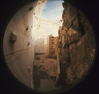
Selected slides and black-and-white negatives from the project were scanned by Luna Imaging (Culver City, CA). Experimentation by CSA had shown that company to be reliable and the quality to be excellent, but neither CSA nor Eiteljorg can supply any information about the scanning procedures, hardware, or software. Some of the color slides were scanned in the latter part of 2000. The others were scanned in the summer of 2003. All black-and-white negatives were scanned in the summer of 2003. All the slides save one were taken by Eiteljorg, with a Nikon F series camera and various lenses, including an 8 mm. fish-eye and a perspective-control 35 mm. lens. The black-and-white negatives were taken with a Mamiya RB67 camera using 120 or 220 film to produce 6 x 7 cm. images.
Data table for Photographs
There is another data table to provide information about the scanned photographs (NewOPphotos.csv). The slides and black-and-white negatives have been described in that table. This table descends from a data base generated using FileMaker Pro 5.0 v 1 to contain data on the scanned photographic images taken of the Older Propylon during Harrison Eiteljorg, II's research and creation of a CAD model. All scanned images are in uncompressed TIFF format. The TIFF file names can be generated from fields f1+f2 (examples "op00001.tif", "oppg6401.tif"). Not all photographs generated during the project were scanned or archived, only those deemed to have sufficient uniqueness to qualify for archival preservation. The data table was first created in October, 2000, and last changed in December, 2003, although the transfer to .csv format did not occur until 2015. At the time of the last alteration, Eiteljorg used FileMaker 6.0, but the file format was not changed as a result.
There are a total of 151 records for 105 scans of slides and 46 scans of medium-format black-and-white negatives. (There is another "record," the label row.)
Photograph data table metadata below (Field, type, and content):
- Field 1: text, indexed - format of original image; entries include "op" for 35 mm slides and "oppg" for medium format negatives, with the "pg" appended because the photographs were taken for photogrammetric analysis of the Mycanaean fortification wall.
- Field 2: text, indexed - a unique number given to each scan.; the negatives range from 6701 to 6750; the slides from 00001 to 00111. (Note that slides op00061, op00083, op00085, op00101, op00104, & op00107 do not exist in the archive.)
- Field 3: text, indexed - date of original image, month and year; example of entry "November, 1989"
- Field 4: text - photographer; only Eiteljorg images (and one taken by Tanoulas but with Eiteljorg's camera) are archived, since they are the only slides for which copyright is available
- Field 5: text - description of image; free text, e.g., "South wall of upper courtyard, plaster and corner detail"
- Field 6: text - film used; e.g., "35 mm. Ektachrome (64)", "35 mm. Kodachrome (uncertain)" with uncertain indicating that the film speed is unknown.
- Field 7: text - the name of the individual/organization who performed the scan and the date of the scan; example of entry "Luna Imaging: October, 2000."
- Field 8: text - the identification assigned to the CD where the image is stored; example of entry "M0004 (0029-3111-0369)". The Mxxxx number is not unique -- there are 2 M0004's. The xxxx-xxxx-xxxx number is unique. These numbers were supplied by the scanning company and have no meaning beyond identifying the CDs.
Data tables linked to CAD model
There are two data tables for information explicitly linked to the CAD model. These tables were originally constructed by Eiteljorg as experiments in the use of attached data tables for CAD models, and the linkages between CAD model and data were implicit. The tables were originally created with MS Access 95 and modified in Access 97. As it became apparent that the attachment system in AutoCAD was not robust and would not withstand migration well (and should therefore be abandoned), the tables were moved to FileMaker (originally 4.0 then 5.0, the format for which is also used by 6.0) via an export/import process using tab-delimited ASCII files. After the transfer to FileMaker, the linkage between CAD file elements and data elements was made explicit with drawing icons and numbers (shown as text in the CAD model) rather than implicit with direct linkage from model elements to data table entries. The tables were last changed in December of 2003. All work on them was done by Eiteljorg. Those tables have been transferred to .csv files (in 2015). One of those files is called OPattDATA.csv and has information about individual blocks (using the layer name of the block with a D in the first position instead of the M that would normally be the first letter of the name of a layer holding a modeled block); the other table is OPcomments.csv and contains data about the model that is broader and less confined as to linkage. (For instance, "This joint shows the change from the second to the third phase. In the second, the prepared joint at the edge of the smooth band was the joint. In the third phase, the stone was re-shaped to permit a vertical joint with the parastas blocks which were added to buttress the revetment blocks which were, by that time, leaning." is one of the comments. It applies to much more than a single block and is related to more than material on a single model layer. The layer holding drawn indicators, such as arrows, to show what materials are being discussed is provided in the table.)
Metadata for OPattDATA.csv (Field, type, and content):
- ID_NUMBER: - number - auto-entered - unique
- DESCR.: text - free entry but generally limited to short descriptions of the particular block that should be clear in light of the layer-naming system
- QUANTITY: text - may be a number or a term such as several (n.a. for not applicable)
- MATERIAL: text - Pentelic marble, poros, trimmed Acropolis limestone, limestone
- BEG_DATE: text - free entry
- END_DATE: text - free entry
- SURFACE: text - free entry description of the surface of the block
- IN_SITU: text - in situ, as trimmed
- USE: text - primary, secondary, revetment foundation
- POSITION: text - free entry, observations about movement of blocks subsequent to installation
- JUSTIFY: text - free entry to explain other observations
- Layer: text - layer containing the block
- NoteLayer: text - the name of the layer containing the note icon
Metadata for OPcomments.csv (Data Fields):
- RECNO: number - auto-entered, unique
- SOURCE: text - scholar responsible for the observation - Eiteljorg, W.B. Dinsmoor, Jr.
- DATE: text - date of the observation
- NOTE1: text - free entry of the observation
- EnteredBy: text - Eiteljorg only at the time of the submission of the table
- NoteLayer: text - name of layer where icon to show linked material exists
- RefLayer: text - the name of the CAD layer on which the referenced material exists (more than one layer name permitted - separated by commas)