Common features of CAD programs
CAD programs are used to create a model of the real world. The term model is used in this guide to refer to the product of a CAD project, that is a computer file which can be re-used to create many individual drawings. The term draw will be avoided in this Guide because it implies the process of making a single drawing rather than the more flexible and complex digital product of a CAD project.
CAD software is widely used for two-dimensional drafting but most CAD software is now capable of creating three-dimensional models, complete with all the complexity of the real world. Whether a model is two-dimensional or three-dimensional it will be a complex layered version of the object under study.
Layering
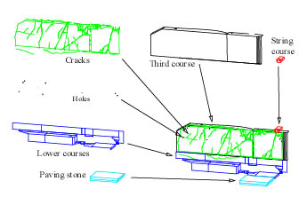
CAD programs enable the parts of a drawing to be held in layers which can be displayed or suppressed on demand. The separate drawing layers created by CAD practitioners can be spatially, temporally or conceptually distinct from one another. For example, in Figure 2 different CAD layers have been used to hold different materials.

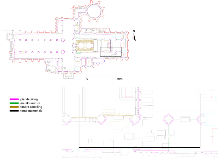
This is particularly valuable when building a CAD drawing which may be used in a multi-disciplinary setting and/or by many different professions. For example, Figure 3 illustrates key structural layers of a York Minster model which make up part of a much more extensive layering scheme. The complete range of 73 layers are not intended to be viewed at once but represent the many professional requirements which the model has been designed to fulfil. For example, the layers evident in this detail include pier detailing, metal furniture, timber panelling, tomb memorials and internal walls.

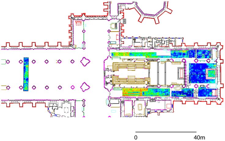
A key development in the increased functionality of CAD has been the potential to incorporate additional raster image data as an integral part of the layering schema. In Figure 4, image data obtained from a Ground Penetrating Radar (GPR) survey provides a valuable additional layer of information. The incorporation of raster image data introduces further archiving considerations for a CAD project. In this case, image data which may be embedded within a CAD layer will also need to be archived separately – ideally adhering to the recommendations of ‘Raster Images‘ guide.

Using layers to build up a model is a crucial part of the successful application of CAD to problems in the humanities. Layers can be used in a variety of ways, for example:
- In archaeology different layers might hold materials from different phases or time periods
- In historic building survey, the masonry of a wall may be shown on one layer, the windows on another, doors on another, and roofing on yet another. Different layers can be used for original parts versus additions, and any missing pieces might be reconstructed on yet another layer
- In theatre design, the different parts of the set may be shown on different layers – for example the stage, the flats, the designs for the scenes painted on the flats, the props and so on.
A thoughtful design of the layering system is one of the most important parts of creating a good CAD model (see CAD systems and Appendix 2). This segmentation into layers makes real analytical use of the model possible and the way that the model is constructed has an enormous impact on the kind of analysis that can be done. Of course, the analysis of CAD layers differs from the types of analysis that can be done with GIS layers (see CAD and GIS).
Multiple CAD files
With large projects, such as an archaeological site or building complex, a single CAD file may become cumbersome and difficult to manage. Where the size of the file causes slow display and manipulation times it may be better to create separate CAD files for the individual elements that make up a large project. Alternatively, separating the elements of a project may also be necessary if the CAD model is being created primarily as a means to build data for another software package to process. For example, it may be desirable to compile the elements at a later stage in the case of virtual reality/animation or GIS projects.
Where separate files are created, links may be established to cross-reference the files (often called cross-references or xref files) to one another to create a composite model. Any number of CAD files linked in this way can be displayed together as if they are part of a single model and, although only one CAD file can be edited at any one time, any changes will be reflected in the composite model.
An advantage of using cross-referenced files lies in the ability of the CAD practitioners to work on small files as they create the elements that make up a large model. Different people may work on different parts of the model at the same time. There are also disadvantages, as editing common aspects of a group of files is more time-consuming than making the same edits in a large file. It is also important to make sure that the layer-naming convention is consistently applied across all of the linked files.
It can also be advantageous to use cross-referenced files for elements whose copyright owner is different from that of the rest of the model, for example where a map is used to provide a background to a plan in a two-dimensional model. The model may be viewed with the element where copyright permission has been granted, e.g. in a publication, but the copyright restricted element may also be removed prior to distribution e.g. when the model is deposited in an archive.
The most significant problem with using multiple CAD files is maintaining the links when files are transferred to a different computer or to a digital archive. If links are established by explicit directory pathways that are specific to the host computer (e.g. c:\projects\pompeii\2000\p211.dxf), when the files are moved to a new computer the links no longer point to the files. Secondary users must re-establish the links between the files by specifying the correct directory pathway. An alternative method is to specify relative directory pathways (e.g. ..\..\p211.dxf), which may ease the problem of moving linked files to a new computer; however, files must be copied in their directories with all relevant sub-directories to maintain the relationship. In addition, some CAD packages enable collections of drawings to be gathered together into projects. Changing the project’s search path can also facilitate the exchange of drawings between users, or deal with different drive mappings to a server location. It is important to document the relationships between cross-referenced files, particularly when depositing a CAD project in a digital archive (see documenting CAD models).
The key issues in considering the use of cross-referenced files are the size of the files and how the elements of the model will be produced. There is no rule of thumb; CAD practitioners will need to experiment with their models to see if they have become too large for current equipment. If speed is not a problem, using cross-referenced files offers no benefit to the end user except where the files are being worked on individually. In that case, it may be desirable to model the individual elements and then to copy these into a single composite model for distribution to others.
Full dimensional precision
Early design systems developed for engineering needed to hold precise dimensions, which were passed to machine tools and used to cut parts. The locations of all points had to be maintained in the computer file as real-world coordinates so that the tool could determine exactly where to cut a part. The computer display was scaled so the user could see the drawing, but underlying the display remained real-world numbers.
CAD programs developed for engineers separated the display of drawings from the underlying numeric data and modern CAD programs also hold the coordinates and measurements for the data-points used to create models in separate data tables. CAD models at different scales may be created from the data-points without the precision of the original data being affected.
Connected data tables
In addition to storing data-points, some CAD programs also allow users to connect individual items within a model to additional information held in external data tables. Such information might include simple annotations or detailed information about items in the model. For example, the individual stones in a building might be connected to a data table that specifies material, date of construction, surface textures, tooling marks, and Munsel colour.
The data table may be linked directly to an element in the model or a layer may be created in the model containing icons. These icons can then be linked to an external file containing explanatory notes. For instance, notes about the prior use of a specific group of blocks, or the blocks used in a certain wall, could be attached to an icon – perhaps an arrow pointing to the blocks in question.
Connecting CAD models to external data tables gives an opportunity to expand on the information in the model or contained in the layer-naming system. Such links are two-way connections and they can add useful analytic capabilities. For example, starting with the database one might obtain the set of all the re-used blocks and then highlight those blocks in the model to display their distribution. Considerable use may be made of such capabilities in excavation recording and intra-site studies, for example by linking context and artefact files to site plans.


