UAV survey
Introduction
This is Part Two of a two-part guide, concerned with establishing good practice when using a small Unmanned Aerial Vehicle (UAV) to produce near vertical photographs of a site, as part of an archaeological survey. This guidance has been created in response to the high degree of interest amongst the UK’s archaeological community in the potential application of new and affordable UAV technology.
Part One of this guide is published by Jisc Digital Media and is concerned with data collection. The guidance presented here discusses data management and archiving, after data has been collected.
Metadata and documentation
As mentioned elsewhere in the Guides to Good Practice, the key to successful digital archiving is thorough documentation of the data; how they were collected, what standards were used to describe them and how they have been managed since collection.
It is expected that, in addition to general Project-level metadata, UAV survey-level metadata and Image set-level metadata will also be archived. All should form part of a completed UAV survey dataset. ADS-specific metadata templates can be found in the ADS Guidelines for Depositors[2].
- UAV survey-level metadata is information that pertains to a unique survey within a project. Camera settings and image properties are included here as most will not be unique to each image.
- Image set-level metadata relates to a specific image set captured as part of a survey. Image set metadata may describe many thousands of individual images.
A further level of metadata is suggested where derived data is also to be archived:
- Processing metadata in order to facilitate reproducibility, Processing metadata describes how new information has been derived from raw data
UAV survey-level metadata
Example of survey-level metadata can be downloaded here.
| Element | Description |
|---|---|
| Survey extent | Given as top right corner and bottom left corner of a rectangle, expressed as decimal degrees, WGS84 datum |
| Survey date/s | Dates or date range of survey expressed as YYYY-MM-DD/YYYY-MM-DD (‘/’ denotes ‘to’) |
| Camera manufacturer | Camera manufacturer |
| Camera model name | Name of camera |
| Camera model number | Model number of camera |
| Shutter speed | At time image set was captured |
| Aperture value | At time image set was captured |
| Focal length settings | At time image set was captured |
| ISO Speed | At time image set was captured |
| Airborne GPS model name | Name of GPS |
| Airborne GPS model number | Model number of GPS |
| Airborne GPS base error rate | As published by GPS manufacturer (both horizontal and vertical accuracy, if known) |
| Terrestrial GPS model name | Name of GPS |
| Terrestrial GPS model number | Model number of GPS |
| Terrestrial GPS base error rate | As published by GPS manufacturer (both horizontal and vertical accuracy, if known) |
| Lens calibration image file name | File names of calibration photographs |
| Lens calibration target file name | If target is to be archived as part of the dataset |
| Lens calibration target information | Target dimensions, creator and other descriptive information |
| Additional UAV survey notes | e.g. name and version of software used to convert .raw images to .tiff or coordinates to GS84 datum |
Image set-level metadata
Example of image-level metadata can be downloaded here.
| Element | Description |
|---|---|
| Image name | e.g. longbarrow-0001.jpg |
| Longitude | Longitude of camera when image was taken. Expressed as decimal degrees, WGS84 datum |
| Latitude | Latitude of camera when image was taken. Expressed as decimal degrees, WGS84 datum |
| Altitude | Altitude of camera when image was taken. In meters, WGS84 datum |
Structure of a UAV survey dataset
Building a standard ‘package’ of data for each low-altitude survey simplifies long-term archiving, makes data easier to share and results easier to reproduce. As a minimum, a primary (raw) UAV survey dataset should include the following items (each is described in detail below).
- Image set-level metadata
- UAV survey-level metadata
- Unprocessed image set
- Lens calibration photographs
- Lens calibration target/s
- Ground Control Point information
- Flight log
Unprocessed image set
Ideally, images would be in a format suitable for archiving, such as .tiff. If images have undergone any form of conversion in order to achieve this, the processing involved should be described under Additional UAV Survey Notes. The required camera metadata, listed above, can typically be automatically harvested from each image, using a batch metadata editing tool such as ExifTool[3].
Image names should include sufficient leading zeros to preserve the order in which they were taken e.g. ‘longbarrow-0001.jpg’ where ‘longbarrow’ is the name of the image set. For more guidance on file naming see Planning for the Creation of Digital Data.
Lens calibration photographs and lens calibration target/s
Photographs of a referenced lens calibration target (see Lens Distortion, below) taken with the same camera and using the same settings, as those used to produced the aerial image set. The target itself (e.g. the chequerboard .pdf which has been printed and photographed) should also be included, if possible.
Ground Control Point (GCP) information
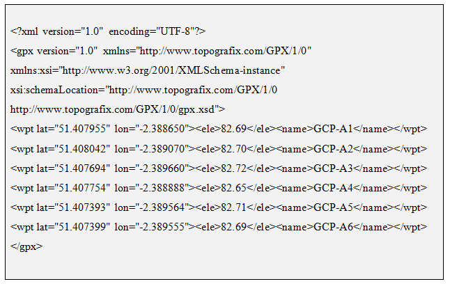
The latitude, longitude and elevation of each GCP, formatted as a .gpx file (expressed as decimal degrees, WGS84 datum). This should give each GCP as a waypoint and associate each with a particular marker, visible in the image set.
Flight log (if produced)
Created by a UAV’s flight controller, this log includes data on the flight path followed during the survey. The log may be produced as a .txt or .log file. Some software (such as Mission Planner[4]) has the ability to automatically generate a ‘flight-path-only’ .gpx files using data extracted from a full Flight Log. These ‘concise’ .gpx files are preferred as they exclude a lot of flight information which is not of relevance.
Derived data
If you intend to archive any form of derived data, in addition to raw data, each derived dataset should be accompanied by its own Processing metadata. Each ‘chain’ of data processing operations should have data Processing metadata. A single data processing chain may result in several new datasets.
Processing metadata
| Element | Description |
|---|---|
| Dataset used | DOI or other unique identifier of data which have been drawn upon |
| Description of data processing software | Name, manufacturer and version number |
| Nature of processing | e.g. rectification methods or transformation types |
| Derived data | DOI or other unique identifier of a derived dataset |
| Description of derived data | e.g. a photogrammetrically generated 3D polygonal mesh. Or a processed subset of photographs, with lens correction applied, transcoded into Geotiff format |
Lens distortion
Every lens distorts a captured image to some degree. Types of distortion include chromatic aberration, vignetting, barrel or pincushion distortion. Determining the type and degree of distortion introduced by a camera lens can be important. Transformations such as orthorectification require this information in order to process images correctly.
Removing lens distortion from an image is a significant image processing operation and so it should not be irreversibly carried out on ‘raw’ data, before it is archived.
Instead, it is important that we include, along with our unprocessed image set, the means for others to measure and remove distortion from our photographs. This approach helps to ensure that poor image correction is not irreversibly applied to our entire aerial image set. For this reason archived datasets should include photographs of a calibration target. The same lens can introduce different patterns of distortion, depending on settings. Therefore when we photograph calibration targets we should ensure our camera has the same settings as for our aerial photographs. Ideally, lens targets themselves should form part of the archived dataset. As a minimum, targets should be referenced in ‘Lens calibration target file name’ and ‘Lens calibration target information’.
Adobe produce the free software Lens Profile Creator which includes a number of printable lens calibration targets. For more information on lens distortion and calibration see Close-Range Photogrammetry Guide.

Extracting image location from a flight log
Ideally, all important metadata would be automatically created for each digital image and, for our purposes, this would include the latitude, longitude and altitude from which it was taken. However, most cameras are not able to ‘geotag’ photographs and even where this is possible, altitude is invariably excluded.
Fortunately there is a work around when using an intervalometer to trigger a camera’s shutter (see Part One of this guide). One piece of information a standard point-and-shoot camera can reliably record is the precise time a photograph was captured. By comparing the time a photograph was taken to the corresponding location of a UAV, extracted from the Flight Log (at the same moment) we can estimate the position of the UAV at the time the image was captured. A margin of error exists but is reduced if we are also able to identify a visible GCP marker in the captured image.
While the extraction of the relevant GPS metadata from a Flight Log can be done manually, software, such as Michael Oborne’s Geo Referencing tool for Mission Planner[6], exists to automate the process.
If a camera is triggered via a cable attached to a flight controller (rather than by an intervalometer function) the Flight Log will contain the ‘trigger shutter now’ command, along with the time the command was issued and the position of the UAV at that moment. This makes determining a photograph’s approximate location even easier.
Summary
Many archaeologists have historically relied on commercially available aerial image sets. This has often proved to be less than ideal. The growing realisation that data collected using a UAV and an inexpensive digital camera can indeed be fit-for-purpose has opened up an exciting new possibility; even a very minor archaeological site can now benefit from a detailed aerial survey.
However, we must ensure that resulting datasets are well-described and are in appropriate formats if we are to overcome the risks of data inaccuracy, incompleteness and incompatibility.
For more on standardising data collection see Part One of this guide, published by Jisc Digital Media.
[2] ADS Instructions for Depositors
[3] http://www.sno.phy.queensu.ca/~phil/exiftool
[4] https://firmware.ardupilot.org/Tools/MissionPlanner/
[6] http://diydrones.com/profiles/blogs/geotagging-images-with-mission-planner

