Case study 2: Symon’s Castle
Symon’s Castle is a 13th century motte and bailey castle on the Welsh borders. Over a ten year period (1985-1994) the total excavation of both the bailey area and the motte top was undertaken in a joint research project between the Archaeology Department at the University of Glasgow (J. Huggett) and the Continuing Education Department at the University College of Wales Aberystwyth (C. Arnold).
Computerisation was undertaken off-site out of season, and included the generation of topographic survey data, a context and artefacts database, and two-dimensional stone-plans and three-dimensional artefact plots created using AutoCAD. On-site equipment limitations meant that all coordinate data, whether for artefact locations, topographic survey, or context recording, were recorded using basic level and tapes. Tests and estimates showed the resulting accuracy to be within ±100mm.
The nature of the site was such that individual contexts were rarely identifiable except in areas that had experienced severe burning – elsewhere, the shallow, leached soil meant that colour differentiation was absent. Major differentiation in stone was apparent, but otherwise structural evidence was extremely slight with few earth-fast timbers. The primary structural evidence consisted of artefacts – the motte-top excavation, consisting of a relatively small area of less than 22 metres by 27 metres, produced over 10,000 individually recorded artefacts, some 3,000 of which are fragments of burnt daub. Many of the burnt daub fragments bear the impressions of wood grain on their flat surfaces, and a number of fragments are characterised by several flat surfaces, either stepped or at right angles to each other. These are interpreted as being derived from horizontally planked timber-framed structures that were caulked on their inner faces with daub. In addition, nearly 700 nails, around 1,200 fragments of lead, and 500 pieces of medieval pottery were found, plus the usual smattering of less common items – some loose change, some buckles and some ironwork, including knife blades and arrowheads, for example.
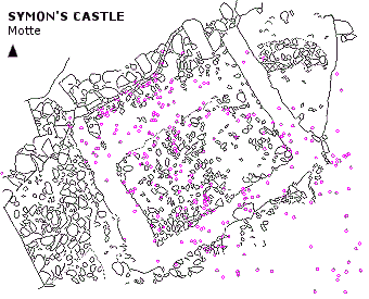
During excavation it became quite clear that the two-dimensional location of artefacts was significant, but only in the sense that locations of types of material became predictable and the suspicion developed that this was related to the presence of otherwise invisible structures. AutoCAD was used initially to generate artefact plots related to stone plans (for example, Figure 1) and across the area of the motte as a whole (Figure ii), with different categories of artefact plotted on different layers and in different colours, enabling combinations of material to be viewed at will. However, this was not as useful a means of visualisation as had been expected since the density of artefacts overwhelmed the plots. There were simply too many items to make an ordinary distribution plot meaningful, beyond the observation of some extremely large concentrations. Yet this information was vital to the understanding of the layout, organisation and nature of use of the site, given the lack of structural evidence.
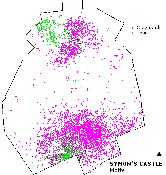
A more analytical means of handling the data was clearly required; specifically a means of calculating summary data according to different criteria and presenting the data in a more meaningful manner. This level of analytical requirement exceeded that available within a typical CAD system (although add-ins for some packages are available as extras), but is well within the capability of a Geographical Information System. In this case, the existing CAD data – plans and artefact distributions – were exported as DXF files for import and manipulation in the IDRISI GIS package.
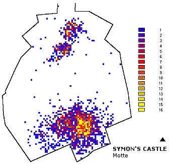
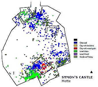
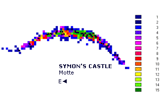
Given the need for resolution and interpretability, contouring was rejected as a technique, as, depending on the interval chosen, patterning was too diffuse or too inexact to be meaningful in terms of the identification of structures and activity areas. Instead the point data was rasterised within the GIS to form incidence matrices for artefact categories which enabled clearer patterns and distinctions to be identified by generating artefact counts within 1 metre, 0.5 metre, 0.25 metre or smaller grid squares (Figure 3). At a basic level, this provided a visualisation method at a range of resolutions which meant that the distributions were more amenable to examination and interpretation. The three-dimensional artefact data could also be used to construct cross-sections in the absence of identifiable context information, which could then be used to test theories about building location and destruction (Figure 4). The end result is the identification of the location of at least one building, and possibly a second, along with a probable cooking area, together with a greater understanding of the structural elements which did survive as identifiable contexts (Figure 5).
This example illustrates the potential interrelationship between CAD and GIS. The distinction between the two types of software is sometimes blurred by the incorporation of GIS or GIS-like add-ins to commercial CAD packages, but the basic differentiation between the kind of data handling and manipulation available within a typical CAD system and a GIS remains. In the CAD version, data were organised in layers which could be used to reveal or hide combinations of data as desired. However, a crucial element within the GIS was the ability to manipulate and combine layers mathematically, creating new categories of data for analytical purposes.
