Two and three-dimensional drawings and models
Two-dimensional models
The difference between two-dimensional drawings and two-dimensional CAD models is that a drawing offers a single representation of the world while a model may be structured into layers that can be viewed together or separately. In addition a model can be produced on paper at virtually any scale. A two-dimensional CAD model (as described in the Deansway case study) may look similar to a two-dimensional drawing of the same plan but in fact the model offers much more flexibility. A series of different views can be produced from the model highlighting different layers. With thoughtful structuring of the CAD layers it is possible to use the model for analysis. For example, the locations of features with given characteristics (e.g. period, phase, material) can be compared, as is illustrated in the Deansway case study.
Three-dimensional drawings and models
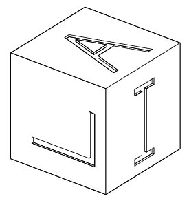
The difference between a two-dimensional drawing and three-dimensional drawings or three-dimensional models is enormous. Figure 1 (The development of CAD) shows a two-dimensional engineering drawing of a child’s wooden block with inset letters on each face. An isometric drawing of the same block (i.e. a drawing showing its three-dimensional nature without foreshortening the sides of the block as they recede) is shown in Figure 5 below. Most people would find the isometric drawings easier to understand than the engineering drawing.
There are essentially three ways of constructing three-dimensional models in CAD:
- Wire-frame modelling
- Surface modelling
- Solid modelling.
Different CAD packages implement these to varying degrees.
Wire-frame models
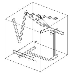
A wire-frame model consists simply of points and lines drawn in three-dimensional space. These define the edges of objects, but there are no defined faces or surfaces. Figure 6 illustrates that these models can be very difficult to use. For example, it can be difficult to tell which lines in a wire-frame model are at the front and which are at the back from a particular viewpoint (the Necker cube effect). A wire-frame model of the older propylon on the Athenian Acropolis would be even more difficult to understand.
Wire-frame models should not be confused with the wire-frame representation of three-dimensional models which have defined surfaces. Surface and solid models may be viewed in CAD software as wire-frames for speed of viewing and manipulation.
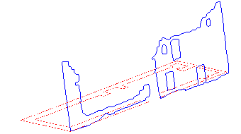
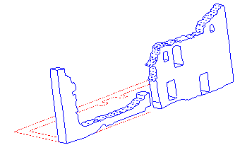
Wire-frame models can provide the basis for other kinds of models. For example, the edges of complex objects can be precisely digitised as a collection of wire-frames and subsequently have surfaces applied to them or be converted into solid objects. For example, Figure 7 is a wire-frame model of part of a castle, derived from an elevation drawing and placed on the floor plan. There is no solidity to the model, it exists only in outline as a series of interconnected three-dimensional points.
Surface models
Surface models are more complex than wire-frame models – as well as defining the edges of objects, the surfaces of the objects are also defined. Hence Figure 5 is a drawing based on explicitly defined surfaces to give the appearance of their real-world shape. These surfaces are opaque so that the lines and faces that would not show in a real-world view are suppressed (a hidden line drawing) – compare Figure 5 and Figure 6. An important CAD feature is that when asked to produce a drawing from a specific vantage point, the program can calculate which lines and surfaces should not appear in the drawing because they would be hidden by intervening surfaces.
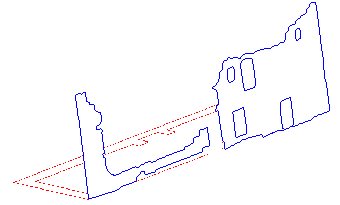
There are many ways of creating surfaces, though in most cases these involve combining small surfaces to create larger, more complex objects. One method involves the construction of small, discrete surfaces that are then combined to make more complex objects (see Figure 8). These may be constructed as wire-frames and surfaces fitted between the edges. For example, Figure 9 shows the same model of a castle wall, but this time the edges have had a (greatly simplified!) surface fitted between them. As a result, when hidden line is applied, the wall now looks more solid.
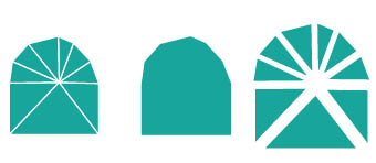
A combination of these approaches is to create templates for surfaces, which can then be swept along pathways to create more complex shapes. For instance, a wire-frame cross-section of a pot could be swept through 360 degrees to create the inner and outer surfaces of the complete vessel. Similarly, Figure i in Case Study 5 (a Digital Terrain Model of Hambledon Hill) is an example of a surface constructed by linking together an array of three-dimensional points to form a mesh.
An alternative method is to use the CAD program’s ability to construct standard geometric solids (boxes, cones, spheres, etc.) automatically, which provides the components that make up the overall shape. Virtually any regular geometric solid can be constructed by most CAD programs and assembled (by Boolean operations of addition, subtraction, etc.) to create more complex solids, a facility that is widely used in design. However, the real world is not made up of regular geometric shapes and recording real-world objects usually requires the construction of large, complex surfaces from small, simple ones. These small surfaces must lie in a single plane; therefore the simplest surfaces are triangular as three points may always be placed in a single plane. Even if a CAD program permits construction of more complex irregular surfaces without using individual planar facets, small surfaces are crucial when modelling very complex geometry.
Solid models
Surface models are constructed from the faces of an object leaving the interior of the object undefined or hollow. In a solid model the composition of the interior is defined – hence it is solid. Although in most views a solid model seems identical to a surface model, a CAD program can produce a cross-section through it. Solid models are created using boolean geometry – adding, subtracting, and ‘differencing’ simple shapes to create more complex ones. In general, solid models are easier to work with than surface models. For example, it is topologically difficult to cut a hole in a surface mesh, but it is easy to ‘carve’ features out of a solid model by subtracting elements from each other. Furthermore, materials can be assigned to solid models and their properties analysed – for example, the mass and centre of gravity of an object can be calculated or its load-bearing capacity determined.
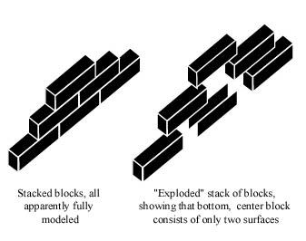
The central block in the middle of the wall depicted in Figure 10 consists of only two visible surfaces. However, all six sides of that stone would need to be surveyed for a solid model to be created. In Figure 11, the original surface model of the wall has been extruded to create a solid wall, and the windows have been created by subtracting them from the wall. The same effect would have been very complex to achieve using a surface model.
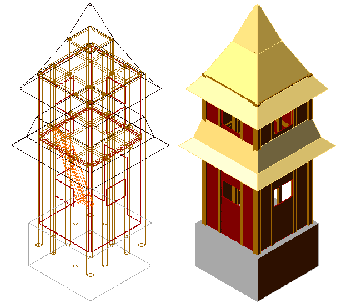
Solid models are also commonly created using a standard ‘toolkit’ of geometric shapes – boxes, wedges, cones, spheres, etc. – which are again combined using boolean algebra to form more complex shapes. For example, Figure 12 is a solid model of a timber tower, which, apart from the roof, is created entirely from boxes using boolean addition and subtraction.
The value of visualisation in public presentations is being increasingly recognised in the humanities, especially in archaeology and architectural history. At the same time, three-dimensional modelling tools are increasingly found in even relatively basic CAD packages. However, it is important to be clear about the purpose of such models. For example, the wall in Figure 11 is a greatly simplified representation of the real world, and while it may provide an adequate visualisation it is far from accurate. It is, however, simple to construct, manipulate, and, with the addition of appropriate surface textures, can provide an effective small-scale model. On the other hand, a fully detailed solid model can rarely be made without dismantling standing structures and the gain from creating such a highly detailed model is often minimal. Such models are complex to make and demanding of computer hardware and are generally only used to address specific structural questions. For example, they might be used in reconstructions of missing structural elements of an historic building, such as in the reconstruction model of the Roman baths in Bath, where the heights and cross-section of the masonry vault were remodelled as a result of the application of physical principles to the solid model (Lavender et al. 1990). Additionally, solid modelling of reconstructions may form the basis of other analytical techniques, for example, acoustic modelling (Campos, Howard and Dobson 2002).
Programs may permit some cross-over between techniques, and users should be familiar with the processes before beginning to build an important model. Learning the intricacies of CAD modelling is best done with one’s own objects and survey data than through any tutorial or sample process. Trying to match real geometry requires the user to understand it at the outset and have a sense of what a good finished model should look like. Although regular solids (boxes, cones, spheres, cylinders, etc.) can often be created with a CAD program, easy-to-use creation tools are rarely useful for modelling real-world objects.
Rendering
Technically, rendering refers to the process whereby a model is displayed on screen from the associated data files. However, the term has come to be used specifically to refer to the process of applying colour, texture and so on to the surface of CAD models. A series of sophisticated processes has been developed for CAD software to illustrate the appearance of objects. These are used to study the results of design choices that affect appearance, e.g. colour, texture, and subtle changes in shape. These programs are particularly important for designing consumer products and in reconstructions, as they enable models to be given a real-world appearance. For example:
- Lighting can be adjusted to see objects under different conditions
- Surface treatments can be applied, e.g. the child’s block could be treated to appear if it were made from wood with white paint to highlight the letters
- Surface textures can be applied, e.g. a photograph can be used to create a bitmap which is applied to the model giving a real-world appearance.
The use of CAD software to render a model allows more ‘realistic’ reconstructions of archaeological monuments. For example, the tower in Figure 12 has been rendered using basic colours and shading, while in Figure 13 more complex textures have been applied. The realistic appearance of such images, however, can be deceptive if read uncritically (Eiteljorg 2000).
