Data capture and field survey for CAD modelling: procedures and techniques
Planning a survey
There are a number of factors which must be taken into account when planning a survey to capture data for a CAD model.
The first consideration is the object to be modelled and the end product that is required. An historic building, a barrow, an excavation plan, some theatre scenery flats and a garden plan each have their different aspects and might be modelled differently in CAD. However, the decision whether to undertake the work in two or three dimensions or to create a wire-frame, surface, or solid model is only partly based on the shape of the object itself. The product that is required also influences the decision. If plan views or elevations are required, then two-dimensional data may be gathered from the outset. An archaeological plan or plan of the standing remains of a building might be made with three-dimensional points but be treated as a plan only; a wire-frame model would be appropriate in such cases.
Data density
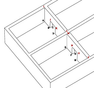
Similarly the number of data-points that are recorded will depend on the type of model that is being produced and the final product(s) that are envisaged, including any visualisation that is required. A three-dimensional model will have at least twice as many points as a plan (see Figure 14). For example, a wall must be surveyed as carefully where it meets the ceiling as where it meets the floor to produce a three-dimensional model, even if it appears to be vertical. An archaeological feature recorded in two-dimensional typically involves a quite dense collection of data points for the outline but relatively few points recording the depth or profile. Such a level of recording cannot subsequently be transformed into a reasonable representation of the original three-dimensional feature unless many more points are recorded in the first place.

Points A-H (blue) would be needed for a plan only, two-dimensional survey
Points I-P (red) would also be needed for a three-dimensional survey
Details within the structure being modelled also affect the density at which data are collected. For example, a wall made of cut marble blocks might require four points for each block while an irregularly surfaced mud brick wall might require a number of points along each edge as well as points spread throughout the surface.
The intended uses of the model should also be taken into consideration when planning the density of data collection. For example, a higher data density will be required if a three-dimensional model is to be used for renderings, virtual reality presentations or other presentations that aim to give a full sense of the object. The scale of the required output also influences the number of points being captured. For example, fewer points are required for a two-dimensional landscape output at 1:10000 than for a similar survey output at 1:1000.
Considerations of time and cost will also influence the type of model that is produced and the number of data points that are captured. When considering data density, practical choices must be made as every added data point complicates the model, the model making, and the end product. Every added point creates some additional costs. However, the value of the model may be compromised if insufficient points are taken because it may not be possible to return to site at a later date. Even if it is possible to return to the site, capturing additional points at a later date represents a much greater cost than during the original survey.
Preliminary modelling
Preliminary modelling of portions of the object may be undertaken to test whether appropriate levels of precision are being achieved. Similar tests may also be undertaken to check whether data are being gathered at an appropriate density, e.g. checking the digital terrain model (DTM).
Hand-measurement surveys
Where moderate levels of precision are required, or on surveys of relatively small objects, traditional hand-measuring techniques may be appropriate. Steel tapes provide excellent precision and accuracy for short dimensions, longer dimensions inevitably introduce error from sagging tapes. Difficulties may also be experienced in measuring along oblique or curved surfaces, or along vertical lines, and so on. Determining longer dimensions by combining shorter ones creates different problems, since errors multiply.
All data-points in a three-dimensional model, of course, must have an elevation but triangulation becomes especially difficult when three-dimensional points are required. It is probably best to measure points in two steps, one to locate the position in plan view only, and another to determine elevation.
With hand-measuring processes, both note-taking to document the process and data gathering requires careful attention. If a three-dimensional model is to be produced more data points are required and these must be fully specified in all three coordinates. Line levels and plumb bobs will be needed to check the orientation on horizontal or vertical planes and, with inclined surfaces, measurements of the inclination are needed. Users should be certain that the geometry of the subject is fully specified; recording for three-dimensional modelling is much more demanding than recording for plans and elevations. It is easy to have a large number of data points with one or two crucial dimensions missing.
Total station surveys
A total station is an electronic theodolite with an electronic distance measuring device (EDM) and usually incorporates a data recorder or data logger. The advantage of these sophisticated surveying instruments lies in the precision that they produce for both long and short measurements. Other advantages of using a total station includes the speed of recording and digital data logging which combine to allow many more data points to be gathered at once in comparison with hand-measurement techniques.
The electronic theodolite displays swing angles (deviation from North) and the angle above or below the horizontal. The EDM sends an infrared beam to a reflector that must be positioned at the point to be surveyed and uses timing algorithms to determine the distance to the reflector. The data recorder records the position of the instrument, the swing angle, the elevation angle, and the distance to the target for each measurement. In addition, the data collector (and often the total station itself) can use simple trigonometric formulae to compute the position of a point surveyed from the known position of the total station and the horizontal and vertical angle and distance, generating a three-dimensional coordinate for the surveyed point.
Some total stations are now able to measure distance without a reflector, although they cannot necessarily make a reading from any surface (as the surface must reflect a significant portion of the light striking it). Therefore, even surveys using this sort of total station will occasionally need a reflector. Some problems are associated with using reflectors; for example, assistants are needed to hold the reflector and data points must be within reach (Eiteljorg 1994; 1995; 1996a; 1996b).
Total stations operate at various levels of precision. Some measure angles to the nearest five seconds, others to the nearest second. Some measure distances to the nearest 2 or 3 millimetres, others to the nearest millimetre with an additional potential error factor related to the size of the measurement. Selecting the correct machine is a matter of matching the expected working distance and conditions, the precision required, the machine capabilities, and price.
The potential error due to angular mis-measurement is very small when compared to the error that may occur in the distance measurement (see Appendix 1).
Transferring data collected from a total station to CAD
Data may be collected using a total station and transferred to CAD in two principal ways:
- transferring data from the data logger incorporated into a total station into CAD software. The points will be surveyed, and the coordinates transferred from the data logger to a computer and from there into a CAD model. The data consists simply of a group of numbered and annotated point coordinates and the operators connect the points to make a useful CAD model. Sketches are made on site just as they would be in a hand survey. Surveyed points must be noted so that the operators of the CAD system will know how to translate isolated data points into the surfaces, lines, arcs, and so on that are the CAD model
- working with a total station connected directly to a computer rather than a data logger. The computer may serve just as a data collector, in which case the system does not differ appreciably from a simple total system. However, the total station data may go directly into a CAD program in which case a CAD model can be generated interactively on screen during survey. With this type of system there is little requirement to make sketches on site during the survey.
When integrating data themes which are derived from survey data, the following should be recorded:
- The source (paper/digital map, GPS, data from mapping agency) and estimated error of survey base station coordinates
- Details of the survey, including date, time and purpose
- Details of the thematic organisation of the survey
- Make and model of instrument used
- Type of survey
- Estimated error terms for the coordinate pairs and (if appropriate) the z-coordinate
- Georeferencing information, overall accuracy of the survey data.
Full details of what to record when collecting survey data are described in Documenting field data capture.
When transferring data from a total station or GPS the data points, two-dimensional drawing information and wire-frame lines will be brought into the CAD model. Building the model from the data points involves the following steps:
- The points are brought into the model, in their own layer(s), with numbers or other unique identifiers
- The points are used to define points in model entities, lines, surfaces, etc.
- Both the original data points and model entities exist in the model
- The data points are no longer useful to the model and may be removed but should be archived for later re-use and accuracy checks. There are a number of options available:
- The points can be kept in a frozen and hidden layer
- The points can be brought into a parallel model, using the same grid system and explicitly related to the principal model, and kept there
- The original transfer files created from the total station may be archived after discussion with an appropriate repository.
Global positioning system receivers
The Global Positioning System (GPS) is a worldwide navigation system based on the Navstar satellite constellation, which is designed and run by the US Dept of Defense. GPS is used for a wide range of applications including navigation, time coordination and surveying. A key concept in achieving accurate positions with GPS is that of differential positioning. If data collected at a fixed GPS receiver with a known position is used in conjunction with data collected simultaneously by a second, mobile, unit the accuracy of the positions recorded by the second unit can be considerably enhanced. This technique is applied over a range of equipment through the use of geostationary satellites, beacons, Ordnance Survey (OS) Active Stations or users’ own base stations. Real-time GPS uses the constantly transmitted data to correct the position reported at the mobile receiver instantaneously, while post-processing systems collect data over a period of time from reference stations and moving units and then process it later.
GPS equipment falls into three broad bands:
- single units for navigation, without recourse to transmitted correction data, produce positions accurate to approximately ten metres
- code only units, usually characterised as GIS collection, or mapping grade, produce positions to better than one metre using broadcast beacon data
- surveying grade equipment uses a range of techniques to fix positions to within one centimetre and is used for large survey control schemes and geodetic measurement.
GPS derived positions are in latitude, longitude and height within the World Geodetic System (WGS84), or equivalent local geodetic systems such as the European Terrestrial Reference System 1989 (ETRS89). In order to use surveys on base mapping, the survey data must be transformed to the local mapping grid e.g. for the UK the OS National Grid (OSGB36). Transformation to the National Grid can be done most accurately using the Precise National Transformation, which is accurate to 0.2m anywhere in the UK. This is available free on their website, or as a computer program and is incorporated in the latest versions of GPS survey resolution software.
Surveying using differential, dual frequency, real-time GPS equipment is typically carried out using a fixed base station composed of a GPS receiver with antenna and radio mounted on a tripod, or a vehicle such as a Land Rover and a rover unit carried by the surveyor in a back-pack or mounted on a pole. Available surveying techniques include the following:
-
- Surveying fixed points, high levels of accuracy (<5mm) can be obtained by longer occupation
- In kinematic mode the receiver can be set to fix points at a pre-set time or distance interval;
- Set in kinematic mode and either carried by the surveyor, or mounted on a moving vehicle, GPS equipment can be used to collect large numbers of three-dimensional points for landscape or terrain modelling. Such data can then be used for site interpretation or reconstruction, or for use in engineering design or for measuring erosion for conservation purposes
- Feature code libraries can be loaded into GPS data collectors, so that surveyed points can be tagged with appropriate codes. These codes can then be interpreted by survey resolution software and lines drawn between points on appropriate drawing layers and of predetermined colour and line-type.
The Ordnance Survey National GPS Network website [1] offers data from the Active Station network for post-processing with the surveyor’s own dual-frequency GPS observations. This allows a surveyor with a single survey grade GPS receiver (base and rover) to determine GPS latitude and longitude at any point in Great Britain and replaces the need to visit at least three trig points to get a good transition from WGS84 to OSGB coordinates.
Direct object scanning
It is technically possible to scan large objects and structures, just as it is possible to scan drawings (see Digitisation: retrospective conversion to CAD from maps, plans and drawings). Many kinds of equipment, including mechanical, magnetic, and optical devices are available for this process but these tend to be expensive.
Devices that are suitable for scanning large objects are heavily automated and they often make the resulting models much more complex than necessary. This is because excess data points are collected, as the points surveyed depend upon a pre-defined grid rather than on logical choices of required points made by a surveyor. Software is used to reduce (decimate) the number of data points by removing those that are not required – for example, points that are not at the edge of a large, flat surface.
It is very difficult to separate the data points collected by automated scanning processes into CAD layers. This is particularly true where large numbers of data points have been collected and they are not tied to specified points in the real world.
Using photographs
The easiest data to obtain from photographs are details from flat surfaces, e.g., the pattern of a mosaic floor or the cracks on a wall. A single photograph can be placed on a digitiser and traced, just as if it were a drawing (see Digitisation: retrospective conversion to CAD from maps, plans and drawings).
Unlike GIS software, CAD software does not include tools to rectify and georeference the raster images produced if the photographs themselves are scanned. For a detailed bibliography and for a full discussion of the issues and techniques involved, including scanning and rectifying aerial photographs, please refer to the GIS Guide to Good Practice.
Photo rectification
If photographs are taken at an oblique angle to the surface then photo-rectification software can be used to perform a mathematical process called a plane transformation.
Although CAD software cannot be used to rectify a scanned photograph, some CAD packages in combination with a digitising tablet can be used to trace and rectify details from a photograph in one step. However, the resulting trace will be a two-dimensional plan and assumes that the underlying surface represented in the photograph is flat, an assumption that may not be appropriate or reasonable in all circumstances. For example, an aerial photograph or elevation photograph may be placed on the digitising tablet, which is calibrated using at least six or more well-separated known two-dimensional coordinate points. As details are then traced from the photograph, they are automatically transformed into the underlying coordinate system. This provides a limited degree of ‘rubber-sheeting’ for oblique photographs. A series of statistics indicating the amount and location of error will typically be provided by the software and should be recorded as an indicator of the overall accuracy of the rectification.
Photogrammetry
Photogrammetry is a technique for producing scaled drawings or models from photographs. It requires, as a minimum, photographs in pairs with a known distance between the two camera positions and very sophisticated equipment. Newer methods, often called close-range photogrammetry or desktop photogrammetry, use three or more photographs and various computer algorithms to locate positions of common points, i.e. points that can be identified in multiple photographs. More information is available from the Close-range photogrammetry guide
When incorporating photographs into CAD models the following information should be recorded:
- full photographic details
- details of the rectification method(s) used
- the software employed including, where possible, specific parameters chosen
- details regarding control points used in georeferencing.


