What is laser scanning?
Laser scanning is the process of recording precise three dimensional information of a real world object or environment. Terrestrial laser scanners are ‘ground based devices’ that can be used to scan at a range of scales from very small objects to very large monuments or entire sites. Laser scanners rapidly sample or scan an object’s surface recording shape and often visual properties (intensity and/or RGB information). The information is returned to the unit as a dense collection of precisely measured XYZ points referred to as a point cloud.
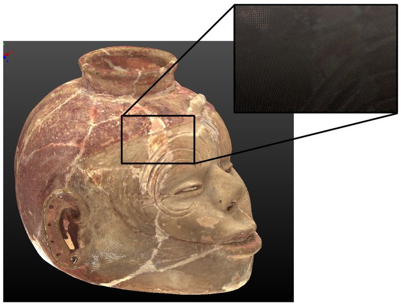
Point clouds produced by laser scanners contain a wealth of information on their own and can also be processed to create accurate 3D models of objects and environments as well as a host of other derivatives that are useful in a wide range of applications. The three main types of terrestrial laser scanning technology are discussed below.
What are the three principal types of scanning technology?
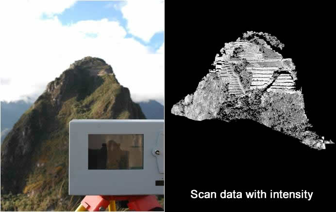
The three principle types of scanning technology include Time of Flight (TOF), Phase Shift, and Triangulation-based systems. Scanning technology is relative to other system factors including acquisition distance, acquisition rate and data resolution/accuracy. Time of flight technology for example has the greatest acquisition range however TOF scanners often have slower acquisition rates and lower accuracy. Phase shift scanners are often categorized as the “fastest” with some instruments scanning over 100,000 points/sec but most phase systems have a maximum range of 80 meters with some systems reaching up to 120 meters. Both phase and time of flight systems can be used in terrestrial scanning applications where larger areas or structures of 5 meters up to multiple kilometers can be surveyed. Triangulation scanners, in contrast, typically have an operating range of less than 5 meters due to the limited field of view shared between the laser and camera. Commonly, triangulation systems are referred to as short range systems and are most suited for scanning smaller objects ranging in size from 1 cm up to 2-3 meters (depending on the instrument). Additional details on the individual scanning technologies are provided below.
Time of flight
Long range laser scanning is typically performed by a Time of Flight scanner. In a TOF system a laser pulse is sent out and a portion of the pulse is reflected from a given surface and returns to the unit. The distance to the surface is calculated from the time of the flight of the pulse. TOF systems can measure over great distances with some systems measuring objects over 1km away although a typical operating range for a TOF system is 5-300 meters. While TOF systems can measure over great distances, they typically have the slowest acquisition rates. The accuracy of TOF technology is determined by the system’s ability to accurately measure the time of the returning signal. While accuracy specifications vary across different systems, typical accuracy for a TOF system is 4-10 mm.
More recent TOF systems include additional RGB capture options either through an internal camera or external camera option. The internal color capture is often ideal because the camera is mechanically or mathematically aligned with the laser scanning system so that the process of projecting the image data onto the point cloud is automatic and accurate. However, the disadvantages of an internal system is that there are often fewer camera adjustment options for achieving consistent color across a group of scans. An external camera option typically involves attaching a digital camera to or in place of a scanner, acquiring a set of images, and then mapping the images onto the data in processing software. The image mapping process can be cumbersome, and if computed incorrectly, can result in subtle misalignments between the point cloud and image data. However, external cameras offer more adjustment options and the images are more easily corrected in an image processing software if necessary. External cameras typically also offer greater image resolution than most onboard systems.
Phase shift
Phase shift scanners emit laser light at alternating frequencies and measure the difference between the emitted and reflected signals to determine the distance to an object. Phase shift systems have a maximum unambiguous range equal to a phase delay of one complete sine wave. This limits the effective range of most phase systems to less than 80 meters or 120 meters for some systems with a typical operating range of 1-50 meters. Phase shift systems are among the fastest laser scanners with many systems claiming a collection rate of up to 100,000 points/second. Commonly these systems also include motorized controls that allow automatic acquisition of surfaces around and above the scanners. As such, these systems are ideal for the scanning of interior rooms or similarly constrained areas. Phase shift systems, like time of flight systems, also typically include internal or external color capture options.
Triangulation
Short range scanners are used to scan individual objects (e.g. pottery vessels, tools etc.), inscriptions and detailed architectural features such as elaborate column capitals. Most short range scanners operate on the principle of triangulation where a laser is emitted and returned to a specific location on a CCD array of an inboard camera. Most triangulation systems come with a set of lenses that alter the field of view of the system. White light or fringe projection systems also employ the principle of triangulation. Triangulation systems typically have an operating range of 0.5-2 meters and can collect data with micron-level accuracy. Most triangulation systems also come with an internal RGB capture option and, for accurate color capture during object scanning, a professional lighting setup must be used.
A useful overview of laser scanning techniques and capabilities can be found in 3D Laser Scanning for Heritage (English Heritage 2007, 7, table 1).
Laser classes and safety
A brief outline of laser classes is provided below however for complete laser specifications, refer to the appropriate US (ANSIZ136[1]) and/or international (IEC 60825[2]) guidelines on laser safety. In short, never stare directly at ANY laser regardless of laser class.
- Class 1: Class 1 lasers are considered safe under all conditions of normal use.
- Class 1M: Class 1M lasers are considered safe under all conditions except for when the beam passes through magnifying optics.
- Class 2: Class 2 lasers are considered safe because they typically cause a ‘blink reflex’ which protects the eye.
- Class 2M: Class 2M lasers are considered safe because of the ‘blink reflex’ unless the beam passes through magnifying optics.
- Class 3R: Class 3R are considered safe if handled carefully and with restricted beam viewing. Class 3R lasers can be hazardous where direct beam viewing is involved.
- Classes 1 – 3R are considered safe for survey in both the U.S. and in Europe.
- Class 3B: Class 3B lasers are hazardous when direct beam viewing occurs though diffuse reflections of the laser are considered non-hazardous. Class 3B lasers are generally not suited for survey applications.
- Class 4: Class 4 lasers cause eye or skin damage as a result of direct beam exposure. Class 4 lasers are also not suited for survey applications.
[1] http://www.z136.org/
[2] https://webstore.iec.ch/publication/62424

